Introduction: ESP32 Handheld Game Console


This instructables show how to use a ESP32 and ATtiny861 to build a NES emulator game console.
Step 1: Hardware Preparation


ESP32 Dev Board
This time I am using a TTGO T8 ESP32 dev board. This board have built-in Lipo charging and regulating circuit, it can help reduce the extra components.
Display
This time I am using a 2.4" IPS LCD. The driver controller is ST7789V and the resolution is 320 x 240. This resolution is best fit for NES emulator 252 x 224 resolution.
Battery
This time I am using a 454261 Lipo battery. 4.5 mm is the thickness of ESP32 dev board, and 61 mm is the width of the board.
Pin Header
A 4 pins male round pin header and a 4 pins female round pin header for connecting I2C gamepad.
PETG Plate
A small PET/PETG plate for supporting the dev board and Lipo battery, you can easily find it in product packing.
Multiple Purpose PCB
2 PCB required, 1 0.4 mm thick for supporting the Display, 1 1.2 mm thick for a I2C gamepad.
Buttons
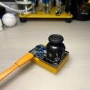
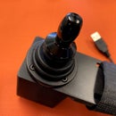
A 5 directions button, 2 small buttons for Select and Start and 2 for A and B button.
I2C Gamepad Controller
This time I use a ATtiny861 microcontroller as an I2C gamepad controller.
Others
1 SMD 12 Ohm resistor, a ISP programmer (e.g. TinyISP)
Step 2: Software Preparation


Arduino IDE
Download and install Arduino IDE if not yet: https://www.arduino.cc/en/Main/Software
ATTinyCore Support
Follow the installation steps to add ATTinyCore support if not yet: https://github.com/SpenceKonde/ATTinyCore/blob/mas...
ESP-IDF
Follow the ESP-IDF get started guide to setup the development environment if not yet: https://docs.espressif.com/projects/esp-idf/en/sta...
Step 3: 3D Printing

Download and print the case: https://www.thingiverse.com/thing:3591170
Step 4: LCD Support


Cut a 24 x 27 holes 0.4 mm PCB for LCD support. Remember reserve some space for folding LCD FPC. Then use some double side adhesive tape fix the LCD on the PCB.
Step 5: Prepare PETG Plate


Cut out a 62 mm x 69 mm PETG plate for dev board and Lipo battery support.
Step 6: Fix ESP32 Dev Board

Use double side adhesive tape to fix dev board on the PETG plate.
Step 7: Fix Lipo Battery

Use double side adhesive tape to fix Lipo battery besides the dev board.
Step 8: Connect Battery & Dev Board

Step 9: Prepare Display Pins

LCD display have many variation form different vendors. Please obtain the correct datasheet and read it before any patch and connection.
Some pins are reserved for touch panel. Since this LCD do not have touch panel, simply cut out those pins can reduce the disturbance.
Step 10: Connect GND Pins


In most case, there are few pins require connect to GND. To reduce soldering effort, I cut a copper tape shape to reach all the GND pins and then soldering altogether.
Step 11: Connect Vcc Pins

There are 2 pins required connect to Vcc, LCD power and LED power. According to data sheet, LCD power can direct connect to dev board 3.3 V pin but LED power operate a little bit lower than 3.3 V. So it is better add a SMD resistor in the middle, e.g. 12 Ohm resistor.
Step 12: Connect LCD & Dev Board Support

use tape connect LCD support and dev board support together. Both support should reserve around 5 mm gap for folding.
Step 13: Connect SPI Pins

Here are the connection summary:
LCD     ESP32
GND  -> GND
RST  -> GPIO 33
SCL  -> GPIO 18
DC   -> GPIO 27
CS   -> GPIO 5
SDI  -> GPIO 23
SDO  -> not connected
Vcc  -> 3.3 V
LED+ -> 12 Ohm resistor -> 3.3 V
LED- -> GND
Step 14: Flash Program


- Download the source code at GitHub: https://github.com/moononournation/esp32-nesemu
- Under source code folder, run "make menuconfig"
- Select "Nofrendo ESP32-specific configuration"
- Select "Hardware to run on" -> "Custom Hardware"
- Select "LCD Type" -> "ST7789V LCD"
- Fill pin settings: MISO -> -1, MOSI -> 23, CLK -> 18, CS -> 5, DC -> 27, RST -> 33, Backlight -> -1, IPS -> Y
- Exit and Save
- Run "make -j5 flash"
- Run "sh flashrom.sh PATH_TO_YOUR_ROM_FILE"
Step 15: I2C Connector


Breakout the I2C pins, ESP32 default I2C pins are:
Pin 1 (SCL) -> GPIO 22
Pin 2 (SDA) -> GPIO 21
Pin 3 (Vcc) -> 3.3 V (no 5 V power while powered by Lipo battery)
Pin 4 (GND) -> GND
Step 16: Assembly Part 1
Follow the video steps to fold and squeeze all the parts into the case.
Step 17: Prototype I2C Gamepad


The program for the I2C Gamepad is very simple, only 15 lines of code. But it is a little bit hard to reprogram the ATtiny861 after soldering, so it is better test it on the breadboard first.
Download, compile and flash the program from GitHub: https://github.com/moononournation/attiny861_i2c_...
Step 18: Build I2C Gamepad


Here are the connection Summary:
ATtiny861       Button
GND          -> All buttons one pin
Pin 20 (PA0) -> Up button
Pin 19 (PA1) -> Down button
Pin 18 (PA2) -> Left button
Pin 17 (PA3) -> Right button
Pin 14 (PA4) -> Select button
Pin 13 (PA5) -> Start button
Pin 12 (PA6) -> A button
Pin 11 (PA7) -> B button
Pin 6 (GND) -> I2C male pin header pin 4
Pin 5 (Vcc) -> I2C male pin header pin 3
Pin 3 (SCL) -> I2C male pin header pin 1
Pin 1 (SDA) -> I2C male pin header pin 2
Step 19: Assembly Part 2

Follow the video steps to install the cover and the I2C gamepad to the main body.
Step 20: Optional: Audio Breakout Pins


ESP32 dev board Pin 25 and 26 is outputting the analog audio signal, it is very easy to breakout the these 2 pins and also power pins (3.3 V and GND) on the top. Then you can patch a earphone to plug on it. Or even you can add an audio amplifier module with speaker to play it loud.
Step 21: What's Next?

NES emulator is not the only interesting thing you can make with ESP32. E.g. you can build a micro python console with it. The only component you need to change is from I2C gamepad to I2C keyboard. I think it is not so difficult to make it with a ATtiny88 controller. You may follow my twitter to see the status.

Participated in the
Arduino Contest 2019
Be the First to Share
Recommendations


Puzzles Speed Challenge

"Can't Touch This" Family Contest
CNC Contest 2020


29 Discussions
3 months ago
Is this LCD Display good to use for the project?: https://www.displaymodule.com/products/dm-tft24-333
It looks there is an additional integrated circuit.
Question 4 months ago
I'm trying to replace your I2C Attiny with the Attiny 2313. I checked out the data sheets and found the corresponding pins that are needed:
Key........Pin (861) ..........861 Pin Deff..............Pin (2313).............. 2313 Deff
Up ........20 ....................PA0 (PCINT) ............12............................PB0 (PCINT)
Down ...19 ....................PA1 (PCINT) ............13............................PB1 (PCINT)
Left ......18.....................PA2 (PCINT) ............14............................PB2 (PCINT)
Right....17.....................PA3 (PCINT) ............15.............................PB3 (PCINT)
Select..14......................PA4 (PCINT).............16............................PB4 (PCINT)
Start....13......................PA5 (PCINT)..............6.............................PD2 (INT0)
A.........12......................PA6 (PCINT) .............18 ..........................PB6(PCINT)
B.........11......................PA7 (PCINT) .............7.............................PD3(INT1)
I2C (header pin 4) 6.....GND...........................10..........................GND
I2C (Header pin 3) 5....Vcc..............................20.........................Vcc
I2C (Header pin 1) 3.....SCL............................19..........................PB7 (SCL)
I2C(Header pin 2) 1......SDA...........................17..........................PB5 (SDA)
I was wondering where I make these changes in the code.
Thanks!
Answer 4 months ago
I did not have that chip, may you try to compile to see is it can fit in the 2k flash first.
Reply 4 months ago
ok, I think I figured out the code changed, but cant figure out the programming part. in step 14:2 "make menueconfig. Cant seem to find that file.
Also, how do you flash the program to the Attiny?
Reply 4 months ago
It should be
Step 17: Prototype I2C Gamepad
You require a USB ISP to program the ATtiny chip.
Question 8 months ago
I'm using ESP-IDF version v4.1-dev-1086-g93a8603c5-dirty while run "idf.py build" was error: "fatal error: nofrendo.h: No such file or directory". Don't "Nofrendo ESP32-specific configuration" option in menuconfig. How can i fix it?
Answer 8 months ago
I have just tried v4 a week before and committed some minor fix. I am still using “make flash monitor” and everything work fine.
Reply 7 months ago
Hi, I'm back.
I'm cloning source from git, and run "make menuconfig" but not working. You can see at below image:
Reply 7 months ago
seems not set idf environment
Reply 7 months ago
It's right. I have not set up the environment yet. Can you support other screen driver?
Reply 7 months ago
I have planned to use Arduino_GFX and migration to Arduino platform, but it is a long journey.
Reply 6 months ago
I'm using this screen with driver ILI9341. How to specified pinout?
Reply 6 months ago
software? make menuconfig
physical connection? read the datasheet
Reply 6 months ago
physical connection, I can't find datasheet of this screen.
Reply 6 months ago
that is the key problem
Reply 6 months ago
this is link of product: https://shopee.vn/product/76666911/2397352619
Reply 6 months ago
This is also 18 pins: https://m.tb.cn/h.V0jn2N8 check if GND pins are the same. then try to apply 2.x V to LED pins
7 months ago
A super project!!!!!!
it should be posted in the instructables contest😎😎😋😋
you will conform win the prize 🏆🏆🥇🥇
10 months ago
Crazy that the ESP32 can run nofriendo, I feel like doing another NES project with it
1 year ago
Brilliant